RSS

Blog posts tagged with 'high-pressure-cleaning'

Pressure Washer Nozzle Chart: What the Colors and Numbers Really Mean
(0) Pressure Washer Nozzle Chart: What the Colors and Numbers Really Mean

Looking for the right pressure washer nozzle? A pressure washer nozzle chart can simplify the process. With so many options—each with different spray angles, orifice sizes, and PSI/GPM ratings—choosing the right nozzle can be tricky. That’s why we’ve put together clear, easy-to-use pressure washer nozzle charts to help you match the perfect nozzle to your machine and job.

Whether you’re removing heavy grime from concrete or gently rinsing off your car, the right nozzle makes all the difference between a professional finish and potential damage.

Pressure Washer Nozzle Color Chart

Pressure washer nozzles are universally color‑coded to make identifying spray angles simple. Each color corresponds to a specific fan angle, and that angle directly affects cleaning power and surface safety. (The color does not indicate nozzle size, more on that later.)

In the chart below, you can see the different colors of pressure washer nozzles, their specs, and uses.

ColorSpray AngleOrifice SizeCommon Use Cases
🔴 Red2.0–6.5+Cutting power; use on metal, concrete only
🟡 Yellow15°2.0–6.5+Removing paint, mildew from hard surfaces
🟢 Green25°2.0–6.5+General cleaning: vehicles, surfaces, decks, patios, fences
⚪ White40°2.0–6.5+Vehicles, windows, soft wood, siding
⚫ Black65°2.0–6.5+Low-pressure soap application

For a more detailed look at high-pressure nozzles, read this full guide


Pressure Washer Nozzle Size Chart

This nozzle chart helps you select the correct nozzle orifice size for your pressure washer based on your machine’s PSI (pressure) and GPM (flow rate) ratings. Getting this right ensures your washer delivers peak performance without damaging the pump or surface you're cleaning.

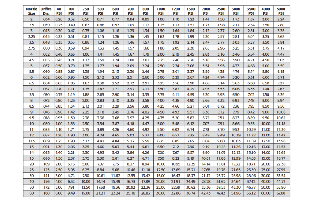
Step-by-Step Instructions to Use This Pressure Washer Nozzle Size Chart

1. Find Your Pressure Washer’s Rated PSI

Look at the top row of the chart. This is your pressure washer’s PSI rating. Common values are 2000, 2500, 3000, 4000 PSI, etc.

2. Find Your Desired GPM or Flow Performance

Look down the columns under your PSI until you find the closest GPM value to your machine’s rating.

If your machine is rated at 3.5 GPM @ 3000 PSI, scroll down the 3000 PSI column until you find the value closest to 3.5.

3. Move Left to Find the Correct Nozzle Size

Once you locate your approximate GPM under the correct PSI column, move left across the row to find the corresponding nozzle size.

Example:

Let’s say you’re using a pressure washer rated for 1500 PSI and 4.0 GPM.

  1. Go to the 1500 PSI column.

  2. Scroll down until you find a value close to 4.0 GPM — follow the row all the way to the Nozzle Size column. In this example, we find the 6.5 nozzle size.

  3. That means you should use a 6.5 orifice nozzle.


While it is important to understand the formula behind this, you can skip the math and use our calculator to find the right nozzle size


Tips on Choosing the Pressure Washer Nozzle

  • Match spray angle to surface - Always start with a gentle, wider nozzle (e.g., 40°) and only go narrower if needed. 

  • Select the proper size - matching the nozzle orifice to your machine is imperative to avoid issues and maximize cleaning efficiency. For more information, refer to this guide on the importance of selecting the proper pressure washer nozzle size. 

  • Consult your pressure washer experts - Dultmeier Sales has power wash experts available to offer guidance and walk you through nozzle sizing if you need help.  


High-Pressure Nozzle Options 

Armed with these nozzle charts, you can browse the variety of color-coded quick-connect pressure washer nozzles and threaded stainless steel nozzle sizes to find the one you need:

(0) Sizing a Pressure Tank - Your Step-by-Step Guide

Pressure tanks are used in a variety of applications, most commonly as an effective way to improve system efficiency. Pressure tanks are so efficient and cost-effective becaue they because they keep pumps from running constantly. In doing so, the pressure-regulating tank increases the longevity of the pump and motor and also reduces maintenance and down time. Let's dive into a step-by-step on how to size a pressure tank.


What You Need to Know Before Starting

In order to properly size your pressure tank, there are a few key data points you should find out:

  1. Flow Rate
  2. Cut-in/Cut-out Pressure
  3. Target Run Time

Most manufacturers suggest a run time of less than one minute if the motor is under 1 horsepower. If the motor is over 1 horsepower, then a run time of 2 minutes or more is common. Always confirm this with your tank manufacturer of choice as guidelines can vary.


Basic Sizing Guidelines for your Pressure Tank

As a rule of thumb, one can follow these guidelines when sizing a pressure tank:

  1. 0-10 GPM: 1 gallon of drawdown per 1 GPM of flow
  2. 10-20 GPM: 1.5 gallons of drawdown per 1 GPM of flow
  3. 20 GPM+: 2 gallons of drawdown per 1 GPM of flow

Drawdown can be defined as the amount of volume loss in the tank as the plumbing system "draws" off this pent up pressure. After all, the purpose of a pressure tank is to maintain pressure in a given system and give the pump a break. This way, the pump doesn't need to run constantly to remain at system pressure. While a pressure tank can appear costly up front, it will save in the long run - less run time for the pump means less maintenance and less money in energy costs.

Pressure tanks come in several orientations - the most common being vertical, horizontal, and inline. Be sure to choose the orientation that best fits your plumbing configuration and available space.

Once we have identified our flow rate in gallons per minute (GPM), have identified our cut-in/cut-out pressure, and confirmed our target run time - we must determine what cut-in/cut-out pressure we want to set the system at.


Pressure Tank Sizing Explained

One key equation to remember when sizing a pressure tank is:


Flow Rate X Run Time = Tank Draw Down Capacity


For example, let's say we have a pump that produces 5 GPM and is powered by a 3/4 HP motor. Since the motor that is less than 1 HP, we'll assume that our tank manufacturer recommends a 1-minute runtime. We want to design this system to cut-in (turn on) at 40psi and cut-out (turn off) at 60psi.

5 GPM X 1 Minute = 5 Gallons of Draw Down (at 40/60PSI)

So, we will need to select a tank that allows for 5 gallons of draw down at a pressure setting of 40PSI cut-in and 60PSI cut-out. A typical vertical tank that fits our needs would be a WOMAX-220. If our plumbing layout would accommodate a horizontal tank better, we could select a WOMAXH-220. This would give us approximately 3.5 minutes of run time before the pump would cycle back on.

Horizontal pressure tanks also have a plastic pump stand so you can maximize space when designing a plumbing system - certainly a nice feature in confined plumbing configurations where space is at a premium.


Relationship Between Pressure & Tank Size

Another important consideration is that as operating pressure increases, the usable drawdown decreases - meaning you’ll need a larger tank to compensate. Pressure and tank size are directly related: higher pressure settings reduce drawdown, which increases the tank size required to achieve your target run time.


Wilo Pumps Logo


After we have these three points determined, we can then proceed with sizing our pressure tank. Pressure settings are another important factor with any plumbing system. The most common pressure settings are 30/50, 40/60, and 50/70. Most manufacturers will have a pressure tank sizing chart that will allow viewers to quickly size a tank's drawdown based upon their system's pressure settings.

If you’d like to explore specifics, we can provide detailed sizing information for the Wilo MaxAir® product line. Just give us a ring during our business hours or visit www.dultmeier.com any time. Below is a cutaway view of a Wilo MaxAir® horizontal tank, highlighting key features that set it apart from the competition and make it one of the top options in the market today.


Cutaway of Wilo MaxAir Horizontal Pressure Tank

Cutaway of Wilo MaxAir Horizontal Pressure Tank


You can view the full offering of Wilo MaxAir® Pressure Tanks right here on dultmeier.com. Have questions about pressure tank sizing or another application? Don’t hesitate to reach out! That’s what we’re here for.

Your Experts in Delivering Fluid Handling Solutions - We Know Flow!

(0) Pulley & Sheave Sizing - All Types of Pump Motors

We commonly receive the call to help assist in properly sizing pulleys and sheaves for pump applications. Generally, this is in high pressure wash applications but we also run into a fair amount of agricultural applications where this knowledge can be leveraged. Pulleys or "sheaves" are commonly used for connecting pumps to motors or engines via drive belts. Most pulleys are cast iron or aluminum construction and are offered in either fixed-bore or tapered bushing styles.

Why is it Necessary to Size Pulleys for Each Application?

For proper operation of any brand or pump type, it is critical to size pulleys and sheaves, correctly, in order to maintain correct RPM, (revolutions per minute). RPM speed is what determines the pump output flow rate - in gallons per minute, liters per minute, etc.

Incorrect pump RPM will adversely affect the pump performance. If the pump is turning too slow - it will not give full performance. Conversely, if the pump is turning too fast, it could cause premature mechanical failures (i.e. valve wear or elastomer failure).

Therefore, it is absolutely critical to ensure correct pulley sizing and analysis of the drive unit, (motor, engine, etc.) relative to the pump. For the sake of this discussion, we will assume standard electric motors at 1750 RPM and standard gas engines at 3400 RPM. Do note, one must determine the rpm of their drive unit to be able to accurately calculate the pulley/sheave size.

If you start with an incorrect figure for RPM - you will size your equipment incorrectly. This could lead to shorter equipment lifespans and/or reduced output flow rates. Thus, ultimately a less efficient system which equates to more down time and added cost of operation. The scope of this post will be focused towards plunger pump applications. We assemble many units using this method in Omaha, Nebraska. Dultmeier Sales is proud to display the Built in the USA logo on our products. Here are just a handful of the pulley-driven pump products that we offer.

The Math of Pulley Sizing

There are complicated formulas for determining pulley ratios but in generic, layman terms, simply divide the driven component (pump) by RPM, the driver component (motor or engine) rated by RPM to get the required ratio. In the example below, the pump RPM is 1070, for full output, while the motor is 1750 RPM.

Therefore, the ratio of the required pulleys would be:


1070 (pump RPM) divided by 1750 (motor RPM) = .611


This means the pulley ratio must be .611 to drive the pump correctly. Hypothetically speaking, if we had a 4 inch pulley on the motor, we would require a 6.55" pulley on the pump. That mathematical equation is as follows: 4" divided by .611 = 6.55"

For the same pump, driven by a gas engine


1070 (pump RPM) divided by 3400 (engine RPM) = .315


If the drive pulley on the engine is 4 inches in diameter, we need to calculate 4/.315 = 12.70. This means that the pump pulley must be 12.70 inches, in diameter, to run the pump at 1070 rpm. You can view a technical page from our catalog here - it will help to further explain the calculation process.

Tapered Bushing vs. Fixed Shaft Bores

Most pulleys, or sheaves, are designed with either fixed shaft bores or tapered bushing hubs. Replaceable hubs fit the required motor or pump shaft size in either inch or mm sizes - depending on the application requirement. These hubs come with bolts to attach them to the pulley, or sheave.


Tapered Bushing


Tapered style hubs simply fit into the pulley opening and then are tightened with two or three set screws, which draw the bushing and pulley together to make one assembly. The pulleys are then attached to the driver (electric motor or gas engine) and driven components (pump). The type of hub, H, SD, SH, etc. must match to a pulley with the same designation for proper fit.

Therefore, make sure to identify what type of hub you have PRIOR to ordering.

Pulleys can be measured in a number of ways. Two of the most common methods are belt pitch and outside diameter (O.D.). When using the, most common A/B, belt pitch method, one must identify both A belt pitch and B belt pitch. This is the pitch diameter of the V-belt you are using, (A/B) is the measurement of how the belt fits into the groove of the pulley.


pitch length


A belts are not as wide as B belts and, therefore, sit lower in the pulley groove. While this may seem as a minor detail - it absolutely affects the ratio measurement when properly sizing a pulley.

Pulleys are available with different numbers of grooves. The number of grooves matches the number of belts that the pulley will accept. A two groove pulley will accept two V-belts. A single groove pulley will only accept one belt.

Again as a general rule, (but not intended to use in every application) single groove pulleys with single belts can be used up to about 5 horsepower. Two groove belts can be used from 5-15 horsepower and three groove belts up to 25 horsepower. Use this as a general guideline but always make sure you consult us if you are unsure of your application needs.


Two Groove Sheaves

Two Groove Pulleys


For correct belt sizing, there are charts available that show the sum of the pulley diameters and the center distance they are apart, from each other. We will be happy to supply you with one of those charts if you wish to have a copy.

For instance, the sum of the two pulleys, in the above electric motor example is 4 inches + 6.5 inches = 10.5 inches. The mathematical equation to figure this out is as follows:


A - Pump Pulley O.D. B - Motor Pulley O.D.


Belt Size = [A*1.57] + [B*1.57] + [2*center distance between pulleys]


76.5 = [4*1.57] + [6.5*1.57] + [2*30]


If the pulleys are 30 inches apart, center to center, then the required belt length would be 77 inches.

As the information above shows, there are many things involved in order to determine the correct pulleys required to drive your pumps correctly. It is important to remember the larger the difference in pulley sizes, the larger the center distance required to maintain minimum contact with the smaller pulley. We would be glad to help with any sizing for your specific applications. Your Experts in Delivering Fluid Handling Solutions - We Know Flow!

(0) The Advantageous Upside to Pure Water

What is Pure H2O?

Crystal clean, pure, and without blemish. If all water entered our appliances, equipment, and food in it's purest form we would have a lot less headaches. Face it - hard water is tough - not just on equipment but on our bodies. If we can introduce pure water into a plumbing system it will accomplish things from reducing friction all the way to keeping maintenance costs lower. Fortunately, we can accomplish this through a process called reverse osmosis.

Think about it this way - let's say you setup two equal plumbing systems but the only factor your change is the water hardness. If you are pumping water that has 450 Parts Per Million (PPM) in System A, versus water that has 10 PPM in System B - which system will outlast the other?

I hope you guessed System B. Common sense tells us the less wear and tear we can put on mechanical pieces of machinery the longer it will last. Therefore, if you have hard water (water that contains more abrasive or suspended particulates) you are going to undoubtedly add to variable expenses in the form of increased operating costs - the upkeep of your equipment will require more routine maintenance and repairs - no way around it. Below you will see a cut-out view of a membrane used in reverse osmosis systems.


Dow Reverse Osmosis Membrane Cutaway


But what if I told you a simple investment, up front, could lower those variable costs and effectively keep more money in your pocket? You keep more money in your pocket by allowing your system to run more efficiently and lessen the likelihood of additional maintenance and repairs costs.

Bottom line - if you can keep your system operating longer and minimize down time, whether that's scheduled maintenance or emergency maintenance, more money stays in your pocket.

Determining Water Hardness

Let's get into the heart of this discussion and throw some numbers out there. Water hardness is determined on parts per million. The EPA allows for 500 PPM in drinking water. Vehicle washing requires, a maximum, 50PPM.

More and more greenhouses are beginning to monitor their water hardness, as well. Greenhouses and farmers across the country need to monitor their pH levels constantly. They do this to ensure that their plants are given the correct ratio of nutrients required to improve yields. By rigorously monitoring the purification of the water supply, an operator can ensure that a clear, and controlled, chemical reaction takes place with their soil matter.

The process of reverse osmosis allows operators and farm/greenhouse managers to effectively oversee this chemical reaction - in a much more efficient manner.

Reverse Osmosis & How it Works

Reverse Osmosis is a process in which microscopic particulates are captured by an extremely fine membrane that allows the solute, in this case, water to pass through. This process is so effective that it can take water with 500PPM and reduce that number to less than 10PPM - and, in many instances we can do much better than that.

This process is achieved through pressurization and, as noted above, extremely fine membranes or filters. The solute is retained on the pressurized side of the membrane and the solvent is allowed to pass through the membrane. The reason this process must occur under pressure is that the solution needs to be forced through the fine holes of the membrane. In many systems there will be multiple stages of filtration.

The first filtration step will occur through an extremely crude manner. In many instances, the process will include a sand bed filtration that is gravity fed. This step is no more complicated than allowing the solution to percolate through a large sand bed - thus extracting many of the large particles that would clog finer filters and membranes - which are downstream in the plumbing system.

The next stage typically involves another filter, or series of filters, that catch particulates and suspended particles that were small enough to pass through the sand bed -which is stage 1 of the filtration process. By implementing this second stage filter the process, in most instances, the solution is ready to actually pass through the finer filters/membranes - thus completing the reverse osmosis process.

Prior to running the solution through the final filtration stages, it must be ran through a "booster pump" that creates the pressurized portion of the system.

Once under pressure, the solution is ran through another membrane or series of membranes. Depending on the water hardness, it might be necessary to use a series of reverse osmosis membranes to reach the desired PPM the operation requires. Basic system components for a reverse osmosis system, used in the vehicle washing industry, can be viewed here.

Upstart University Video Explanation

Here is a video from Upstart University on how reverse osmosis can benefit farmers and greenhouse managers.


For further product questions or inquiries about reverse osmosis systems and or replacement components and parts - don't hesitate to contact us or check out our website at Dultmeier.com - Thanks for stopping by and take care!

(0) Horsepower Sizing for Various Pumping Applications

Have you ever wondered how to quickly and accurately solve the problem of correctly sizing the horsepower for a pumping application? In this post we offer a short lesson in yet another technical application that our Sales Team deals with on a daily basis. We practice the principle of horsepower sizing almost every day at Dultmeier Sales.

In order to correctly size the horsepower for an application one must perform the following equation(s) in order to calculate. For positive displacement pumps we use the output pressure & flow rate required to determine the required horsepower. Centrifugal pump horsepower sizing is calculated using different methodology. We will elaborate on centrifugal pumps later in this post.

For positive displacement pumps, such as plunger, piston, diaphragm, or roller pumps we want to take the pressure (psi) x flow rate (gpm) divided by the constant for the particular type of pump, (which is based on the general efficiency of the pump type).

Determine the Type of Pump & Drive Option

For Piston and Plunger pumps, the constant factor is 1460. Roller pumps we use 1030. Lastly, Diaphragm pumps we use a factor of 1370. These constant factors are used for pumping water solutions - if we get heavier or more viscous solutions than water - our factors will need to be altered.

Centrifugal and Gear pumps can vary greatly and must be engineered to the specific application. That being said, we can look at some examples further down the line in this post.

We also need to consider the type of drive option that will be used. For instance, when using an electric motor versus a gas or diesel engine, there are varying drive constant factors, as well. More on this below in the post.

Horsepower Sizing Examples Explained

Example 1: Plunger pump rated flow is 4 gpm at 2000 psi. "EBH" or Electric Brake Horsepower required would be 4 x 2000 = 8000 divided by 1460 = 5.48. This equation shows us that we would require an electric motor with at least 5.48 horse power output to allow the pump to operate at peak performance. In this instance you would most likely need to use a 7-1/2 HP electric motor as most motor brands are generally 1HP, 1.5HP, 2HP, 3HP, 5HP, 7.5HP, 10HP, 15HP, 20HP, 25HP, etc.

It is important to note that electric motors have a rated horsepower and your specific application will have a required horsepower. Required specifies the horsepower needed to produce the desired output flow and pressure. While, rated horsepower defines the horsepower at which the motor is rated. For instance, if the application requires a 13 HP motor, one would need to select a motor that is rated for 15 HP (there is not an electric motor rated for 13 HP or 14 HP). Best practice is to select a motor that has a rated horsepower which exceeds your required application horsepower.

Example 2: Diaphragm pump rated flow is 12 gpm at 500 psi. The EBH would be calculated as such: 12 x 500 = 6000 divided by 1370 = 4.38 This would require an electric motor with at least 4.38 horsepower output to allow this pump to operate at peak performance.

Specialty Applications - Diesel Transfer Horse Power Sizing

For calculating gas or diesel engine horsepower requirements, a general rule is to take EBH required x 2.0. Example 1 above would require 5.48 EBH x 2. 0 = 10.96 engine horsepower requirement. Therefore you would need a gas or diesel engine that will develop at least 10.96 horsepower to allow the pump to operate at peak performance.

You can look at some diesel transfer units (centrifugal pump) that we have sized specifically for flow rates at the nozzle. We have multiple offerings that are designed to produce flow rates through a plumbing system. When calculating, we figure in the Total Dynamic Head of the plumbing system. In the case of our Diesel Transfer Skids, that means the pressure loss through the hose reel, 32ft of hose (inside diameter varies based upon specific unit) and a discharge nozzle. We use a self-priming centrifugal pump in these skid systems. When dealing with self-primer centrifugal pumps a safe efficiency factor to use is 50% efficiency.

When using gas or diesel engines to power pumps, depending on specific brands, "engine" horsepower requirements could be reduced slightly in some instances. For instance, some engines may have a higher compression or provide more torque as a result of enhance production practices. This is generally a smaller factor but something to consider when powering a pump with an engine.

Centrifugal Pump Horsepower Sizing

A major difference in sizing centrifugal pumps lies in the size, or trim, of the impeller. Based upon the solution, desired flow rates, and TDH in the plumbing system - we will size a pump to have a certain impeller trim and this directly correlates to the required horse power.

Generally speaking, we use pump curves to assist in sizing a centrifugal pump for a specific application. A pump will ALWAYS operate on it's curve. That's why it is vital to accurately determine our desired output flow rate, TDH, and solution being transferred. All of these factors, and actually many more like temperature and viscosity can, and will, affect the required horse power and impeller size of a centrifugal pump.

We have multiple tools at our disposal to assist with this process. One of them comes from a supplier of ours, Wilo. Dultmeier Sales' expertise paired with the expertise of Wilo helps us to provide a value-added service for our customers in pump/motor sizing for many applications.

Standard Efficient vs. Premium Efficient Electric Motors

Another important note to make is the difference between a standard efficient motor and a premium efficient motor. With the passing of Department of Energy regulations in January 2020 - many pumps (specifically straight centrifugal pumps) are now held to a certain degree of efficiency standards. The main goal being power consumption. Premium efficient motors are designed to be just that...much more efficient than a standard efficient motor.

Many pump manufacturers have since, or are in the process of switching, to premium efficient motors to assist in ensuring their pump products meet the mandated efficiency standards. Some manufacturers were able to re-engineer their pumps to meet the regulations - while others needed to redesign the pumps and upgrade to premium efficient motors.

Be aware, in some larger NEMA frame motors, the premium efficient option can boast a larger footprint. If your motor footprints do not match, this could cause an issue when you go to install the replacement motor. This is an important thing to consider when replacing standard efficient motors.

Service Factor in Electric Motors

Lastly, we want to consider the service factor in an electric motor of choice. A common service factor that many motor manufacturers use is 1.15. This means if your horsepower is rated to 20 HP then you actually have some leeway to go slightly beyond the rating - if necessary. 20 HP x 1.15 Service Factor = 23 HP. If our application had a required horsepower of 22.25 HP we could select this example motor with a service factor of 1.15.

While it's certainly not advised to select the example 20 HP motor in this instance - it could work. We would always caution on the side of error and advise the end user to select a rated 25 HP motor.

We certainly hope that this post provided useful content. As always, should you have any questions about pump sizing - don't hesitate to call us at 888-677-5054. Be good out there.

(0) Disinfecting Foamer Excites Poultry Industry
Leading Poultry Producers have recently approved the patent pending design of the JBI Poultry Disinfectant Foaming Trailer. JBI Services partnered with Dultmeier Sales in early 2017 to transform this idea and design into reality.